To add the diameter symbol in AutoCAD, type %%c where the symbol should go in any text or dimension text, and AutoCAD draws Ø in its place.
This guide covers the control code, the Unicode string \U+2205, the Symbol menu in the MText editor, the Character Map, the DIMDIAMETER command, a dimension style prefix, a reusable block, and fixes when the symbol will not display.
The fastest way to add the diameter symbol in AutoCAD
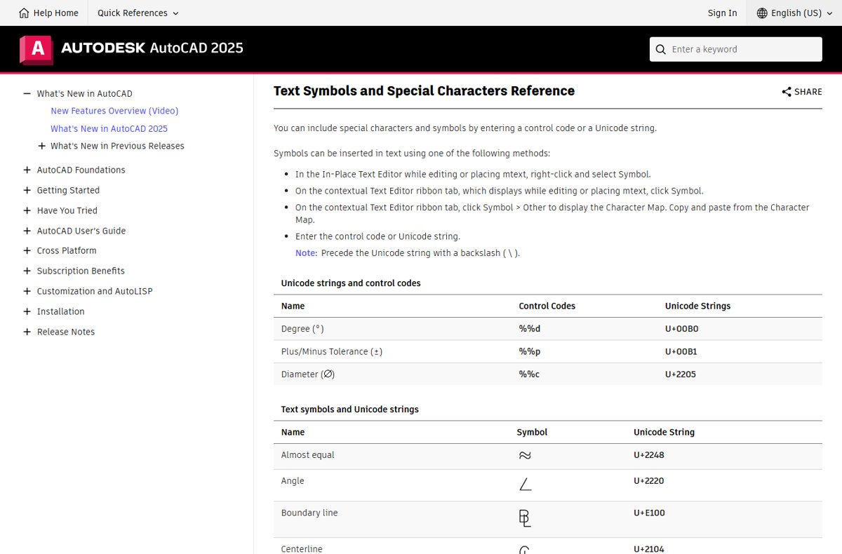
The %%c control code works in single-line text, in multiline text and in dimension text. Autodesk lists it as the circle diameter dimensioning symbol.
- Start the TEXT or MTEXT command, or double-click existing text to edit it.
- Place the cursor where the symbol belongs, usually right before the number.
- Type
%%cfollowed by the value, for example%%c25. - Finish the text. AutoCAD shows Ø25 instead of the code.
The code stays stored in the text, so editing it later shows the symbol, not the code.
Methods to Add Diameter Symbol in AutoCAD
Every route below ends with the same Ø character. Pick the one that matches what you are annotating.
| Your situation | Use this | Why |
|---|---|---|
| Dimensioning a circle or arc | DIMDIAMETER command | Adds Ø automatically, no typing |
| A note or label in single-line text | Type %%c |
Three keystrokes, no menus |
| A note in multiline text and you prefer menus | Text Editor tab > Symbol | Pick it from a list that also shows its code |
| Pasting text from another program, or scripting | Unicode string \U+2205 |
Same character AutoCAD stores for Ø |
| Hunting for a variant glyph in a specific font | Symbol > Other (Character Map) | Shows every character in that font |
| Linear dimensions of shafts or holes shown in side view | Dimension style prefix %%c |
Every dimension in that style gets Ø |
| Fixing one existing dimension | Double-click the dimension text | Edits only that dimension |
| A graphic Ø you want identical across drawings | A block saved with WBLOCK | Reusable file, same size and layer each time |
Understanding the Importance of Diameter Symbol
The diameter symbol tells the reader that a value is a diameter, not a radius or a width. In AutoCAD it is one of three built-in dimensioning symbols with their own control code.
| Symbol | Meaning | Control code | Unicode string |
|---|---|---|---|
| Ø | Diameter | %%c |
\U+2205 |
| ° | Degree | %%d |
\U+00B0 |
| ± | Plus/minus tolerance | %%p |
\U+00B1 |
A diameter dimension created with DIMDIAMETER already carries the symbol. You add it by hand only in notes, linear dimensions and edited dimension text.
Using the Diameter Command
DIMDIAMETER creates a diameter dimension for a circle or an arc. Autodesk states that the diameter symbol appears automatically in front of the dimension text.
- Type
DIMDIAMETERand press Enter. - Select the circle or arc.
- Optional: enter M (Mtext) or T (Text) to add words around the measurement before you place it.
- Click to place the dimension line and text.
From the ribbon, click Annotate tab > Dimensions panel > Dimension, select the circle, then enter d for Diameter at the prompt.
Inserting the Diameter Symbol with Special Characters
Control codes start with two percent signs. They work with AutoCAD's SHX fonts and with PostScript fonts, and %%c also works inside multiline text.
- Type
TEXTand press Enter. - Click the start point, then set the height and rotation angle at the prompts.
- Type
%%c50 THRUfor a 50 mm through-hole note. - Press Enter twice to end the command.
- Check the text reads Ø50 THRU.
Additional Tips
Control codes can be combined in one string. These combinations come up most often in hole and shaft callouts.
| What you want | Type this | Result |
|---|---|---|
| Diameter with a plus/minus tolerance | %%c20%%p0.1 |
Ø20±0.1 |
| Underlined diameter note | %%u%%c20 BORE |
Ø20 BORE, underscored |
| Overscored value | %%o%%c20 |
Ø20 with a line above |
| A percent sign in the same note | %%c20 %%% |
Ø20 % |
Underscoring and overscoring switch off automatically at the end of the text string, so no closing code is needed.
Using Unicode or ASCII Code
Ø is not part of the 128-character ASCII set, so there is no ASCII code for it inside AutoCAD. Use the control code or the Unicode string instead.
| Code type | What to type | Where it works | Notes |
|---|---|---|---|
| Control code | %%c |
TEXT, MTEXT, dimension text, dimension prefix | Shortest option |
| Unicode string | \U+2205 |
TEXT, MTEXT, dimension text | The backslash is required |
| Decimal code | %%nnn |
TEXT | nnn is the decimal Unicode value of a character; %%c is simpler for Ø |
| Character Map | Copy and paste | MTEXT editor | Opened with Symbol > Other |
Using Unicode Input in AutoCAD
The Unicode string is useful in scripts, LISP routines and spreadsheets you paste into AutoCAD, because it spells out the exact character.
- Start TEXT or MTEXT, or open existing text for editing.
- Place the cursor before the value.
- Type a backslash and the code:
\U+2205. - Type the value, for example
\U+220512. - Finish the text and confirm it reads Ø12.
Leave out the backslash and AutoCAD prints the letters U+2205 as plain text.
Using the Text Editor to Insert Diameter Symbol
The contextual Text Editor tab appears while you place or edit multiline text. Its Symbol menu lists common symbols next to their control code or Unicode string, which also covers the right-click special character menu.
- Type
MTEXT, press Enter and drag a text box, or double-click an existing mtext object. - Click where the symbol belongs.
- On the Text Editor tab, go to the Insert panel and click Symbol.
- Choose the diameter entry, listed with
%%c. - Alternatively, right-click inside the editor and select Symbol, then the same entry.
- Click outside the editor to finish.
The same Insert panel has Field, which opens the Field dialog box. Fields insert live values such as dates or object properties, not symbols, so use Symbol for Ø.
Using the Character Map
The Character Map shows the full character set of each font on your system. Use it when you want the glyph from one specific font.
- Open the MText editor as described above.
- On the Text Editor tab, click Symbol > Other.
- Choose the font your text uses.
- Select the Ø character and click Copy.
- Back in the editor, right-click and click Paste.
Characters pasted this way depend on the chosen font. %%c is safer when the drawing may be opened with a different font later.
Using Dimension Styles to Display Diameter Symbols in AutoCAD
A prefix in the dimension style adds Ø to every linear dimension in that style. This suits drawings of shafts, pipes or holes shown from the side, where you use linear dimensions for diameters.
- Step 1: Type
DIMSTYLEand press Enter to open the Dimension Style Manager. - Click New, name the style, for example
DIA-LINEAR, and click Continue. Or select an existing style and click Modify. - Step 2: Open the Primary Units tab and type
%%cin the Prefix box under Linear Dimensions. - Step 3: Adjust the text settings on the Text tab: pick a style in the Text Style list whose font carries Ø, such as Romans or Isocpeur.
- Step 4: Click OK, select the style, click Set Current, then click Close.
- Draw linear dimensions with
DIMLINEAR; each reads Ø plus the measurement.
Autodesk notes that a prefix overrides default prefixes, including the one diameter and radius dimensions use. Keep this prefix in a separate style so your radius dimensions do not show Ø.
Inserting the Diameter Symbol Manually
Use this to add Ø to one dimension that already exists without changing its style.
- Double-click the dimension text to open the in-place text editor.
- Place the cursor in front of the measurement.
- Type
%%c, or click Symbol on the Text Editor tab and pick the diameter entry. - Click anywhere outside the text box to save.
When creating a dimension, you can do the same at the prompt: enter T (Text) and type %%c<>. The <> brackets keep the measured value live, so it updates if the geometry changes.
Creating and Using Blocks for Diameter Symbols in AutoCAD
A block is useful when you want a drawn Ø graphic at a fixed size and layer, or a text-based one you reuse across many drawings.
- Step 1: Draw the diameter symbol: a small circle crossed by a slanted line, or a TEXT object containing
%%c. - Step 2: Type
BLOCKand press Enter to open the Block Definition dialog box. - Enter a Name, such as
DIA-SYMBOL. - Click Pick Insertion Base Point and click the centre of the symbol.
- Click Select Objects, select the symbol, press Enter, choose Convert to Block, and click OK.
- Step 3: To save it for other drawings, click Insert tab > Block Definition panel > Write Block, or type
WBLOCK, set the Destination path and click OK. - Type
INSERTto open the Blocks palette and place the block wherever you need it.
Advanced Tips
These options in the Block Definition dialog box and related commands make a diameter block behave better on plotted sheets.
| Option | Where | Effect |
|---|---|---|
| Annotative | Block Definition > Behavior | The block scales with the annotation scale of each viewport |
| Attribute definition | Add before running BLOCK | Prompts for the diameter value each time you insert the block |
| WBLOCK file | Insert tab > Write Block | Lets every drawing and every user insert the same symbol |
| Retain vs Convert to Block | Block Definition > Objects | Keeps the original geometry or swaps it for the block |
Customizing the Diameter Symbol in AutoCAD
The look of Ø comes from the font, and how you trigger it depends on the route. Change it at the level that matches the scope you want.
| What to change | Where | Scope |
|---|---|---|
| Font of the symbol in notes | STYLE > Text Style dialog > Font Name > Apply |
All text using that style |
| Font of the symbol in dimensions | Dimension Style Manager > Modify > Text tab > Text Style | All dimensions in that style |
| Automatic prefix on linear dimensions | Using the Dimension Style Manager: Primary Units tab > Prefix = %%c |
All linear dimensions in that style |
| One dimension only | Double-click its text and type %%c |
That dimension |
| Keyboard shortcut | No built-in key inserts Ø; %%c is the typed shortcut |
Anywhere text is accepted |
Autodesk notes that changing the font file of a text style updates every text object using that style when the drawing regenerates.
How to check the diameter symbol displays correctly
- Zoom in on the text or dimension and confirm it shows Ø followed by the value, not
%%cor\U+2205. - Double-click the text; the editor should show the symbol, confirming AutoCAD converted the code.
- For a dimension, change the circle size with grips and confirm the value after Ø updates.
- Plot or export a test sheet and confirm Ø appears in the output.
Troubleshooting Common Issues with Diameter Symbols in AutoCAD
Issue 1: Diameter symbol not displaying correctly
The text style uses a font that does not contain the Ø glyph, or the Unicode string lost its backslash.
- Check the typed code is
%%cor\U+2205with the backslash. - Type
STYLEand press Enter. - Select the text style, then pick a font Autodesk lists for its symbols, such as Romans, Simplex, Isocp or Isocpeur, in Font Name.
- Click Apply, then Close.
Issue 2: Inability to insert the symbol via keyboard shortcut
AutoCAD has no default shortcut key for Ø.
- Type
%%cwherever text is accepted. - In the MText editor, right-click and select Symbol instead.
- For repeat use, save the symbol as a block and insert it from the Blocks palette.
Issue 3: Text font changes causing display issues
Changing the font of a text style updates every object using it, and the new font may lack the glyph.
- Undo the change or type
STYLEto open the Text Style dialog. - Pick a font from Autodesk's symbol-capable list in Font Name.
- Click Apply so existing text updates.
- Type
REGENand press Enter to redraw.
Issue 4: Difficulty in automating diameter symbols in multiple annotations
Adding Ø to each dimension by hand does not scale.
- Create a dimension style with
%%cas its Prefix on the Primary Units tab. - Select the dimensions that need Ø.
- Open the Properties palette and set their dimension style to the new style.
Issue 5: Compatibility with exported files
Autodesk states that text containing control codes is not plotted as PostScript text, though it is still plotted accurately.
- Export and open the result to check the symbol appears.
- Expect the symbol to arrive as plotted geometry rather than editable PostScript text.
- Use a font from Autodesk's symbol list in the text style before you export.
Best Practices for Using Diameter Symbols in AutoCAD Drawings
Use DIMDIAMETER for circles and arcs, a %%c prefix in a dedicated dimension style for linear diameters, and %%c typed by hand only for notes and one-off edits. The command and the style add Ø automatically, so every annotation matches. Blocks or attributes suit repeated graphic symbols, and one symbol-capable font keeps clarity and consistency across the drawing set.
Frequently Asked Questions
How do you type the diameter symbol in AutoCAD?
Type %%c before the value in any text or dimension text. AutoCAD replaces the code with Ø, so %%c25 displays as Ø25. The code works in single-line text, multiline text and dimension text.
Is there a symbol for diameter?
Yes. Diameter is written with Ø, a circle crossed by a slanted line. AutoCAD stores it as Unicode U+2205 and inserts it with the %%c control code or the Symbol menu in the text editor.
What's the symbol for diameter in AutoCAD's Unicode list?
Autodesk lists the diameter symbol as Unicode string U+2205. Type it with a leading backslash, \U+2205, in text or dimension text. Without the backslash, AutoCAD prints the letters instead of the symbol.
How do you use the diameter symbol in a dimension?
Use the DIMDIAMETER command, which adds Ø automatically. For a linear dimension, enter T at the prompt and type %%c<>, or set %%c as the Prefix on the dimension style's Primary Units tab.
How do you create a diameter symbol you can reuse?
Draw the symbol or place text containing %%c, then run BLOCK to turn it into a block. Save it with WBLOCK so other drawings can insert it from the Blocks palette.
How do you enter the diameter symbol in multiline text?
While editing mtext, click Symbol on the Insert panel of the Text Editor tab and pick the diameter entry. You can also right-click in the editor and select Symbol, or type %%c.
How do you make the diameter symbol show instead of a wrong character?
Switch the text style to a font Autodesk lists for symbols, such as Romans, Simplex, Isocp or Isocpeur. Type STYLE, change Font Name, click Apply, and the text updates after a regeneration.